MediaPipe Instant Motion Trackingを用いた、AndroidにおけるARエフェクトの実現

はじめに
はじめまして。
KINTO テクノロジーズで KINTO Unlimited Android アプリを開発している JR.Liang です。
本記事では、KINTO Unlimited アプリにて提供する「これなにガイド」スキャン機能の AR エフェクトについて、Android における技術的な検証を紹介します。
特に MediaPipe のソリューションを用いて幅広い Android デバイスで AR エフェクトを実現した実装にフォーカスします。
これなにガイドとは
「これなにガイド」は AR(拡張現実)を活用して、車内スイッチの用途や使い方をテキストと動画で案内する機能です。紹介動画をご覧ください。 上記の紹介動画は iOS アプリでの動作を示しています。スイッチ上に表示された黄色の丸 🟡 が、AR 技術で実現した仮想コンテンツです。
機能全体の仕組みは以下の流れです。本記事では 3 番目(描画)に関する内容を扱います。
1. アプリのカメラを起動、カメラ画像を取得
2. 機械学習における物体認識を用いて、車内のスイッチを検出
3. 検出した座標を元に、ボタンとテキストをフレーム上に描画
4. ボタンをタップして、当該スイッチのテキストと動画を表示
Android AR 技術検証の経緯
当初の Android 版「これなにガイド」のスキャン機能では、Canvas を利用して毎フレーム検出される座標に描画する実装でした。そのため検出の時間差により、スマホ(カメラ)を動かすと描画のズレが生じていました。
2D Canvas
幸い、MediaPipe のソリューションである Instant Motion Tracking モジュールで素早くかつ安定した AR エフェクトを実現できることがわかり、Android への導入を検証しました。
3D OpenGL
MediaPipe Instant Motion Tracking
MediaPipe は Google が開発したオープンソースの ML フレームワークで、顔検出・手のトラッキング・姿勢推定などリアルタイム映像処理のソリューションを提供します。
その中の Instant Motion Tracking は、現実世界のシーン上に 3D 仮想コンテンツをリアルタイムで正確に配置できる AR トラッキング機能です。初期化や厳密なキャリブレーションが不要で、静止面や動いている面の上にコンテンツを置くことが可能です。
Android + MediaPipe AR アーキテクチャ
CameraX で取得したフレームを Instant Motion Tracking に渡し、TensorFlow Lite で物体検出した情報を元に AR コンテンツを描画・追従させるパイプラインです。
MediaPipe ライブラリの作成
MediaPipe では Bazel を使用してパッケージをビルドします。Android に適合する AAR として書き出してアプリに組み込みます。
AAR をビルドする BUILD ファイルを作成し、instant_motion_tracking を基盤とした定義を記述します。
load("//mediapipe/java/com/google/mediapipe:mediapipe_aar.bzl", "mediapipe_aar")

mediapipe_aar(
    name = "mediapipe_ar",
    calculators = ["//mediapipe/graphs/instant_motion_tracking:instant_motion_tracking_deps"]
)
MediaPipe は C++ が中核のため、C++ ランタイムである libc++_shared.so を AAR に同梱する必要があります。
また Instant Motion Tracking では画像処理ライブラリ OpenCV を利用し、AR トラッキングを行います。
上記サードパーティのライブラリを含めて、以下のコマンドで AAR をビルドします。
bazel build -c opt --strip=ALWAYS \
    --host_crosstool_top=@bazel_tools//tools/cpp:toolchain \
    --fat_apk_cpu=arm64-v8a \
    --linkopt=-Wl,-z,max-page-size=16384 \
    //path/to/the/aar/build/mediapipe_ar:mediapipe_ar.aar
- 市場に流通している Android デバイスは主に arm64-v8a アーキテクチャのため、AAR のサイズを抑える目的で
fat_apk_cpu=arm64-v8aにします。 - C++ ライブラリの 16KB page-size に対応するため、
max-page-size=16384を追加します。
また AAR を利用するにはグラフ構造を定義するファイル(binarypb)が必要です。
bazel build -c opt mediapipe/graphs/instant_motion_tracking:instant_motion_tracking.binarypb
Instant Motion Tracking の導入
AAR をアプリに組み込んで、Android 側の実装を解説していきます。
下記は AAR に組み込んだ instant_motion_tracking の全体構造です。
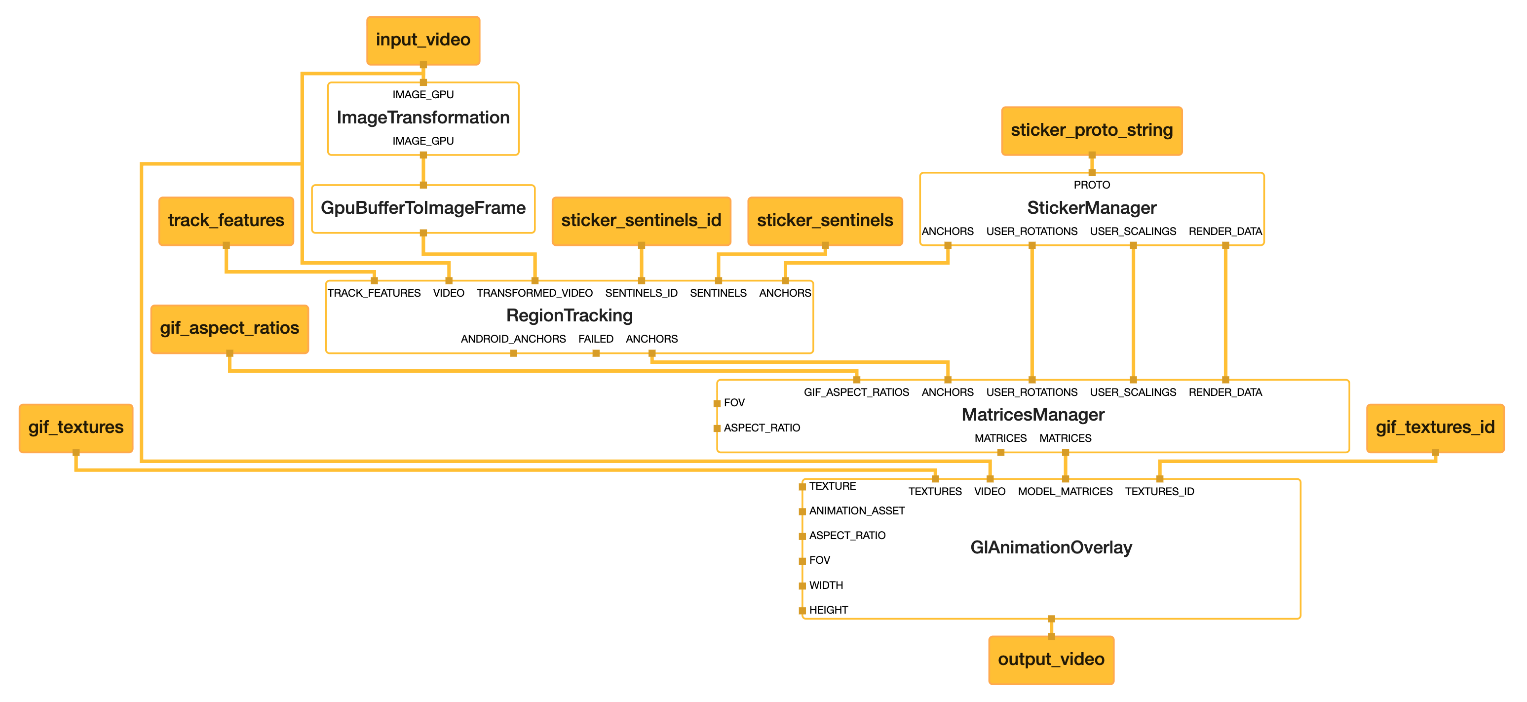
instant_motion_tracking.pbtxt の構成
グラフ定義ファイル instant_motion_tracking.pbtxt は、Calculator(処理ノード)・入出力ストリーム・サイドパケットの 3 要素で構成されます。
Calculator
各 Calculator がパイプライン上でどの処理を担うかを示します。
| Calculator | 役割 |
|---|---|
| ImageTransformationCalculator | カメラフレームを 320×320(FIT)にリサイズ。物体検出モデルの入力サイズに合わせる |
| GpuBufferToImageFrameCalculator | GPU テクスチャを CPU の ImageFrame に変換。TensorFlow Lite 推論に使用 |
| StickerManagerCalculator | Sticker Proto をパースし、初期アンカーの座標・回転・スケール・レンダリング種別に分解 |
| RegionTrackingSubgraph | ボックストラッキングでアンカー位置を追従。内部に TrackedAnchorManagerCalculator(アンカー管理)と BoxTrackingSubgraphGpu(GPU トラッキング)を持つ |
| MatricesManagerCalculator | トラッキング結果・回転・スケール・FOV・アスペクト比から OpenGL 用 4×4 モデル行列を生成 |
| GlAnimationOverlayCalculator | モデル行列とテクスチャを用いて、元のカメラフレーム上に AR コンテンツを OpenGL で描画し output_video として出力 |
input_stream / output_stream
input_stream はフレームごとに Android 側から送信するデータ、output_stream はグラフの処理結果です。
| ストリーム名 | C++ 型 | 方向 | 用途 |
|---|---|---|---|
input_video |
GpuBuffer | Input | カメラフレーム |
sticker_proto_string |
String(Serialized Proto) | Input | ステッカーの座標・スケール等(Sticker Proto) |
sticker_sentinels |
vector<int> | Input | 座標をリセットするステッカー ID の配列 |
gif_textures |
vector<AssetTextureFormat> | Input | AR コンテンツの Bitmap テクスチャ配列 |
gif_aspect_ratios |
vector<float> | Input | 各テクスチャのアスペクト比 |
output_video |
GpuBuffer | Output | AR 描画済みフレーム |
input_side_packet
input_side_packet は初期化時に一度だけ渡す定数で、グラフ実行中は変化しません。
| パケット名 | 用途 |
|---|---|
vertical_fov_radians |
カメラの垂直 FOV(ラジアン) |
aspect_ratio |
カメラのアスペクト比 |
width / height |
カメラ解像度 |
gif_texture |
デフォルトテクスチャ(1x1 プレースホルダ) |
gif_asset_name |
AR テクスチャ描画用のポリゴンメッシュ(.obj)ファイル名 |
Android への導入に当たって、公式サンプルのコードを参考にします。
1. 初期化
MediaPipe を使用する前に、ネイティブライブラリの読み込みとアセットマネージャーの初期化が必要です。
companion object {
    init {
        System.loadLibrary("mediapipe_jni")
        System.loadLibrary("opencv_java4")
    }
}

// onCreate 相当の処理
AndroidAssetUtil.initializeNativeAssetManager(context)
mediapipe_jni: MediaPipe のコア処理を行う JNI ライブラリopencv_java4: AR トラッキングに使用する OpenCV ライブラリinitializeNativeAssetManager: ネイティブコードからアセット(binarypb 等)にアクセスするために必要
2. カメラを起動する
公式サンプルを参考に、以下の順序でパイプラインを構築します。
データフロー: CameraX → ExternalTextureConverter → FrameProcessor → SurfaceView
2.1 EGL 環境と FrameProcessor の初期化
val eglManager = EglManager(null)
val frameProcessor = FrameProcessor(
    context,
    eglManager.nativeContext,
    "instant_motion_tracking.binarypb",
    "input_video",
    "output_video"
).apply {
    videoSurfaceOutput.setFlipY(true)
    setInputSidePackets(
        mapOf(
            "gif_asset_name" to packetCreator.createString("gif.obj.uuu"),
            "vertical_fov_radians" to packetCreator.createFloat32(fovRadians),
            "aspect_ratio" to packetCreator.createFloat32(resolution.width.toFloat() / resolution.height.toFloat()),
            "width" to packetCreator.createInt32(resolution.width),
            "height" to packetCreator.createInt32(resolution.height),
            "gif_texture" to packetCreator.createRgbaImageFrame(createBitmap(1, 1))
        )
    )
}
EglManager: OpenGL ES の EGL コンテキストを作成・管理。MediaPipe のグラフ内 GPU Calculator(GlAnimationOverlayCalculator等)が OpenGL で描画するために必要FrameProcessor: EGL コンテキストを受け取り、グラフの読み込み・入出力ストリームの管理・フレームごとのグラフ実行を行うinstant_motion_tracking.binarypb:.pbtxtを Bazel でコンパイルしたグラフ定義バイナリinput_video: MediaPipe グラフへカメラフレームを入力output_video: グラフで処理(AR 描画など)された映像を出力videoSurfaceOutput.setFlipY(true): OpenGL とカメラの Y 軸方向が逆のため、出力映像を上下反転して正しい向きにするsetInputSidePackets: グラフのinput_side_packetに対応する定数をまとめて設定。カメラの FOV・アスペクト比・解像度など、グラフ実行中に変化しない値を初期化時に一度だけ渡す
gif_asset_nameは AR テクスチャを描画するためのポリゴンメッシュ(頂点データ)、ここでは公式サンプルのgif.obj.uuuを利用
2.2 カメラ映像の変換パイプライン構築
val externalTextureConverter = ExternalTextureConverter(eglManager.context, 2).apply {
    setFlipY(true)
    setConsumer(frameProcessor)
    setDestinationSize(resolution.width, resolution.height)
}
val cameraHelper = object : CameraXPreviewHelper() {
    override fun getCameraCharacteristics(context: Context?, lensFacing: Int?) = cameraCharacteristics
}.apply {
    setOnCameraStartedListener(onCameraStartedListener)
    startCamera(
        context,
        lifecycleOwner,
        CameraHelper.CameraFacing.BACK,
        externalTextureConverter.surfaceTexture,
        Size(resolution.height, resolution.width)
    )
}
ExternalTextureConverter: カメラのGL_EXTERNAL_OESテクスチャを MediaPipe が処理できる標準テクスチャに変換setFlipY(true): カメラ映像の上下反転を補正setDestinationSize(resolution.width, resolution.height): パイプラインの処理サイズはポートレート座標(例:960×1280)で指定
CameraXPreviewHelper: CameraX でバックカメラを起動し、Converter の SurfaceTexture に出力startCamera(targetSize = Size(resolution.height, resolution.width)): CameraX はセンサー座標(ランドスケープ)を期待するため、width と height を入れ替えて渡す
公式サンプルでは CameraXPreviewHelper をそのまま使用し、内部で CameraManager からカメラ特性を取得します。
本実装では getCameraCharacteristics をオーバーライドし、事前に取得済みの CameraCharacteristics を直接渡します。これにより FOV やアスペクト比の算出に使うカメラ情報を、アプリ側で一元管理できます。
2.3 出力先SurfaceViewの設定
SurfaceView(context).apply {
    holder.addCallback(object : SurfaceHolder.Callback {
        override fun surfaceCreated(holder: SurfaceHolder) {
            frameProcessor.videoSurfaceOutput.setSurface(holder.surface)
        }

        override fun surfaceChanged(holder: SurfaceHolder, format: Int, width: Int, height: Int) {
            val displaySize = cameraHelper.computeDisplaySizeFromViewSize(Size(width, height))
            val (displayWidth, displayHeight) = if (cameraHelper.isCameraRotated) {
                displaySize.height to displaySize.width
            } else {
                displaySize.width to displaySize.height
            }
            externalTextureConverter.setDestinationSize(displayWidth, displayHeight)
        }

        override fun surfaceDestroyed(holder: SurfaceHolder) {
            frameProcessor.videoSurfaceOutput.setSurface(null)
        }
    })
}
SurfaceHolder.Callback: SurfaceView のライフサイクルに応じて FrameProcessor の出力先を管理surfaceCreated: FrameProcessor の出力先として Surface を設定surfaceChanged: 画面回転・サイズ変更時に出力解像度を調整surfaceDestroyed: リソース解放
3. 検出座標をグラフに渡す
物体検出(TensorFlow Lite 等)で得られた座標を MediaPipe グラフに渡し、AR コンテンツを配置します。
3.1 グラフから変換済み画像を取得
MediaPipe グラフ内で ImageTransformationCalculator と GpuBufferToImageFrameCalculator によって変換された画像を addPacketCallback で受け取り、物体検出に使用します。
frameProcessor.addPacketCallback("transformed_input_video_cpu") { packet ->
    packet ?: return@addPacketCallback
    // 変換済み画像を物体検出(TensorFlow Lite)に渡す
    val bitmap = PacketGetter.getBitmapFromRgba(packet)
    objectDetector.detect(bitmap) { detections ->
        // 検出結果を処理
    }
}
transformed_input_video_cpu: 変換後の画像を出力するストリーム名
3.2 座標の正規化
物体検出結果のピクセル座標を、MediaPipe が期待する正規化座標に変換します。
// ピクセル座標 → 正規化座標 (0.0〜1.0)
val normalizedX = pixelX / imageWidth.toFloat()
val normalizedY = pixelY / imageHeight.toFloat()
3.3 Sticker Proto の構造
Instant Motion Tracking では、AR オブジェクトの位置情報を Protocol Buffers 形式で定義します。
message Sticker {
  int32 id = 1;        // ユニークID
  float x = 2;         // 正規化X座標 (0.0〜1.0)
  float y = 3;         // 正規化Y座標 (0.0〜1.0)
  float rotation = 4;  // 回転角度
  float scale = 5;     // スケール
  int32 render_id = 6; // レンダリングID
}

message StickerRoll {
  repeated Sticker sticker = 1;
}
3.4 フレームごとにパケットを送信
setOnWillAddFrameListener を使用して、各フレーム処理前に検出座標をグラフへ送信します。
frameProcessor.setOnWillAddFrameListener { timestamp ->
    with(frameProcessor.graph) {
        // 検出された物体の座標情報をパケットとして送信
        val stickerRoll = StickerRoll.newBuilder()
            .addAllSticker(detectedObjects.map { detection ->
                Sticker.newBuilder()
                    .setId(detection.id)
                    .setX(detection.normalizedX)  // 0.0〜1.0
                    .setY(detection.normalizedY)  // 0.0〜1.0
                    .setScale(detection.scale)
                    .build()
            })
            .build()

        val stickersPacket = packetCreator.createSerializedProto(stickerRoll)
        addPacketToInputStream("sticker_proto_string", stickersPacket, timestamp)
    }
}
FrameProcessor.setOnWillAddFrameListener: 各フレームがグラフに送られる直前に呼ばれるコールバックFrameProcessor.graph.addPacketToInputStream: 入力ストリームにパケットを追加sticker_proto_string: グラフ定義で指定された入力ストリーム名
4. テクスチャ(Bitmap)の描画と送信
位置情報と同時に、AR コンテンツとして描画する Bitmap テクスチャもグラフに渡します。
4.1 Bitmap テクスチャの生成
検出された各スイッチに対して、丸アイコンとラベルテキストを含む Bitmap を生成します。
val bitmap = createBitmap(width.toInt(), height.toInt()).apply {
    with(Canvas(this)) {
        concat(Matrix().apply {
            preScale(-1.0f, 1.0f, width / 2f, height / 2f) // X軸を反転して描画
        })
        drawCircle(circleX, circleY, CIRCLE_RADIUS, circlePaint)
        drawRect(rectLeft, rectTop, rectRight, rectBottom, backgroundPaint)
    }
}
Matrix().preScale(-1.0f, 1.0f) で Bitmap を左右反転しています。以下の IMU 行列に合わせるためです。
float imu_matrix[9] = {
  -1.0f, 0.0f, 0.0f,  // X軸 → 反転(-X)
   0.0f, 0.0f, 1.0f,  // Y軸 → Z軸へ
   0.0f, 1.0f, 0.0f   // Z軸 → Y軸へ
};
この行列は OpenGL モデル行列(4x4)の回転成分として使われ、Y/Z 軸の入れ替えと X 軸反転でテクスチャをカメラ平面に平行に固定します。
本来はデバイスの IMU センサーから回転行列を受け取り、端末の傾きに追従させます。
本実装では固定値にすることで常にカメラ正面を向く(ビルボード効果)ようにし、(0,0) の -1.0 による X 軸反転を Bitmap 側の preScale(-1.0f, 1.0f) で打ち消します。
4.2 テクスチャの送信
// テクスチャ画像(Bitmap配列)
val texturesPacket = packetCreator.createRgbaImageFrameVector(
    renderStickers.map { it.bitmap }.toTypedArray()
)
addPacketToInputStream("gif_textures", texturesPacket, timestamp)
// アスペクト比(テクスチャの縦横比)
val aspectRatiosPacket = packetCreator.createFloat32Vector(
    renderStickers.map { it.aspectRatio }.toFloatArray()
)
addPacketToInputStream("gif_aspect_ratios", aspectRatiosPacket, timestamp)
PacketCreator.createRgbaImageFrameVector: 複数の Bitmap を RGBA 形式のパケットに変換gif_textures: テクスチャ画像の入力ストリームgif_aspect_ratios: 各テクスチャのアスペクト比(正しいスケーリングに必要)
公式サンプルでは createRgbaImageFrame を使用して単一のテクスチャをグラフに渡します。
本実装では、複数の検出オブジェクトに対応するため createRgbaImageFrameVector で複数テクスチャを同時に送信し、gif_aspect_ratios も createFloat32Vector で各テクスチャに対応するアスペクト比の配列を渡すよう拡張します。これにより、検出された各スイッチに異なるラベル(テキスト付きBitmap)を正しい縦横比で表示できます。
ここまでで AR コンテンツをカメラ上に表示できました。
5. 座標の更新
トラッキング中のステッカー座標を更新するには、新しい座標を持つ sticker_proto_string と、リセット対象の ID を含む sticker_sentinels を同一 timestamp で送信します。TrackedAnchorManagerCalculator が該当 ID のトラッキングボックスを破棄し、新しい座標でトラッキングを再開します。
// 更新した座標で Sticker Proto を再構築
val stickersPacket = packetCreator.createSerializedProto(stickerRoll)
addPacketToInputStream("sticker_proto_string", stickersPacket, timestamp)

// リセット対象のステッカー ID を送信
val stickerSentinels = packetCreator.createInt32Vector(updateIds)
addPacketToInputStream("sticker_sentinels", stickerSentinels, timestamp)
公式サンプルでは sticker_sentinel で単一のステッカー ID を送信します。
本実装では sticker_sentinels として createInt32Vector で複数のステッカー ID を配列で渡すよう拡張し、物体検出で座標が更新された複数のステッカーを同時にリセットできるようにします。
最後に
以上が MediaPipe Instant Motion Tracking を用いた技術的な実装解説でした。決して容易に導入できる手法ではありませんが、本機能の要件に対して Android に最も適した解決策だと考えています。
以前に ARCore の検証も行いましたが、ARCore は SLAM 技術による事前の 3D マッピングに時間を要し、素早くかつ安定した AR エフェクトの実現には適さなかったため、検証を断念しました。
両フレームワークの違いを以下にまとめます。AR 技術の検討で参考になれば幸いです。
| 項目 | Instant Motion Tracking | ARCore |
|---|---|---|
| 仕組み | 2D ボックストラッキング + OpenGL 描画 | 環境マッピング + 平面検出(SLAM) |
| デバイス要件 | OpenGL ES 対応であれば動作 | ARCore 対応デバイスのみ(Google 認定必須) |
| 安定性 | 検出座標に依存するため補正が必要 | 空間認識が高精度で安定 |
| 導入コスト | Bazel ビルド・C++ Calculator のカスタマイズが必要 | SDK 導入のみで比較的容易 |
| オープンソース | あり(Apache 2.0) | なし(プロプライエタリ) |
| カスタマイズ性 | Calculator の追加・変更で柔軟に拡張可能 | SDK の API 範囲内に限定 |
| パフォーマンス | 軽量(2D トラッキングベースのため CPU/GPU 負荷が低い) | 高負荷(環境の 3D 空間マッピングを常時実行) |
| 学習コスト | 高い(Bazel・C++・OpenGL・Protocol Buffers の知識が必要) | 低い(Android SDK の知見で導入可能) |
関連記事 | Related Posts
Compose化した画面の初期化処理、initブロックでやるか?LaunchedEffect(Unit)内でやるか?
Figma MCPとClaude CodeでAndroidのUI構築を高速化
Jetpack Compose Animation Techniques: Enhance App Impressions with Minimal Code Changes
小規模なコード修正で効果的にアプリの印象を改善する、Jetpack Composeのアニメーション追加のテクニック

InlineContent in Jetpack Compose: The Hidden Gem for Complex Text UI
必須! 既存のAndroidアプリをedge-to-edge対応にするための速習ガイド